How to use a SG90 / SG90 Servo with an Arduino Bot Universe
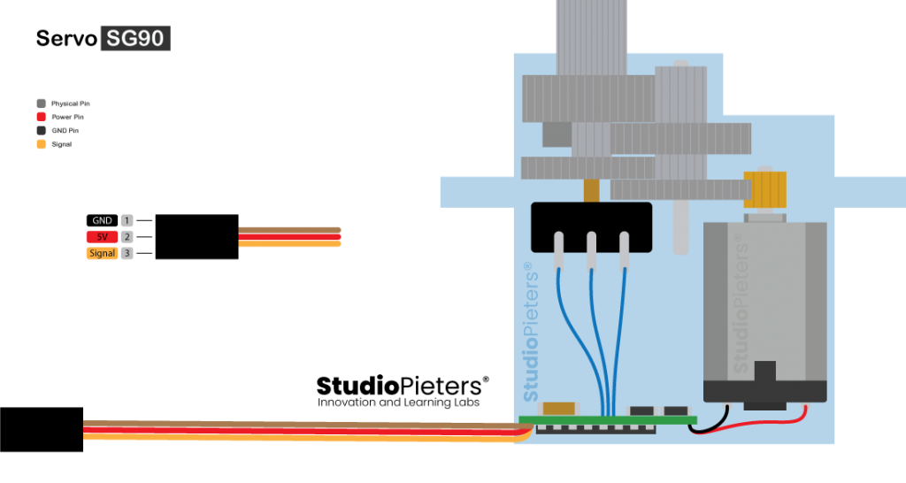
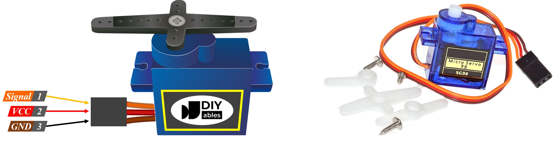
SG90 Servo Pinout
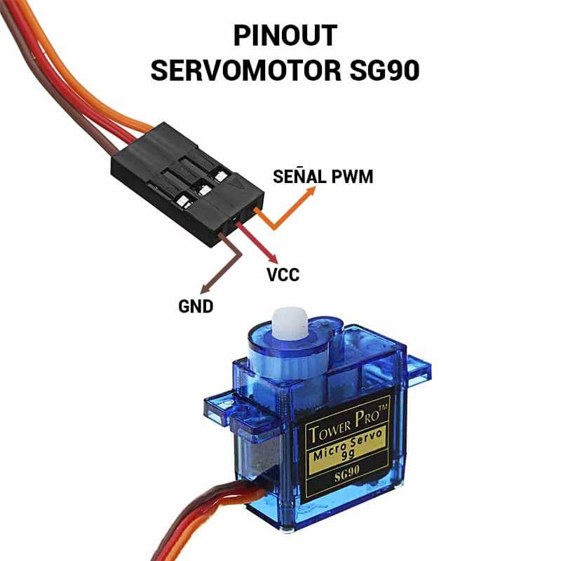
Servo Motor Pinout (Wires) Servo Motor Wire Configuration TowerPro SG-90 Features Operating Voltage is +5V typically Torque: 2.5kg/cm Operating speed is .1s/60° Gear Type: Plastic Rotation : 0°-180° Weight of motor : 9gm Package includes gear horns and screws SG-90 Servo Motor Equivalent
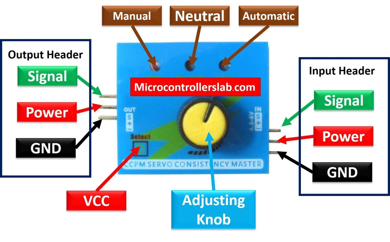
CCPM Servo Tester Pinout, Modes, Features, How to test Servo Motors?
Servo Motor Pinout. Let's take a look at the servo motor pinout in this picture down below which have 3 pins. Servo Motor Pinout . GND: This pin is common ground for the motor and the Arduino. 5V: This pin is 5v which power the servo motor. Control: This pin is used as an input to control the servo motor.
Arduino wire library explained erogai
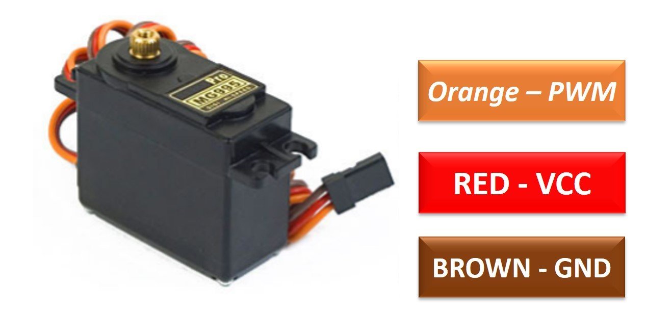
Servo Motor Pinout Servo motors typically have three connections, her is the PIN Out of the Tower Pro™ Micro Servo S9 (SG90). he wires varies between servo motors, but the red wire is always 5V and GND will either be black or brown. The control wire is usually orange or yellow. Arduino Example
MG995 Servo Motor Pinout, Interfacing with Arduino, Features, Examples
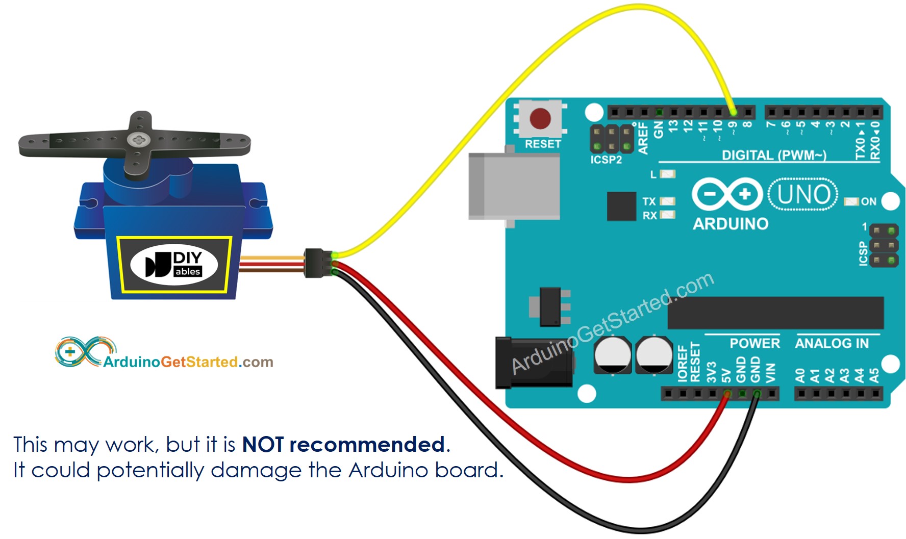
Here's the circuit diagram for this example. We simply need to connect the control pin of the servo to any digital pin of the Arduino board, connect the Ground and the positive wires to the external 5V power supply, and also connect the Arduino ground to the servo ground.
Arduino Servo Motor Arduino Tutorial
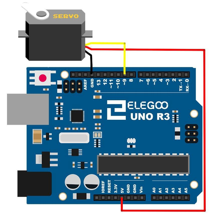
Schematics For emphasis, the connection is further described below. SG90 Servo - Arduino VCC (Red wire) - 5V SIG (yellow/orange) - D8 GND (Black/Brown) - GND The signal pin was connected to the digital pin 8 of the Arduino because it is a PWM pin. Servo directions are sent from the microcontroller to the servo motor as PWM pulses.

Wiring Diagram Multiple Servos Arduino Meag
Servo Motor Pinout Servo motors typically have three connections, as outlined below. GND serves as a common ground for the motor and the logic. 5V is a positive voltage that powers the servo. Control is an input for the control system.
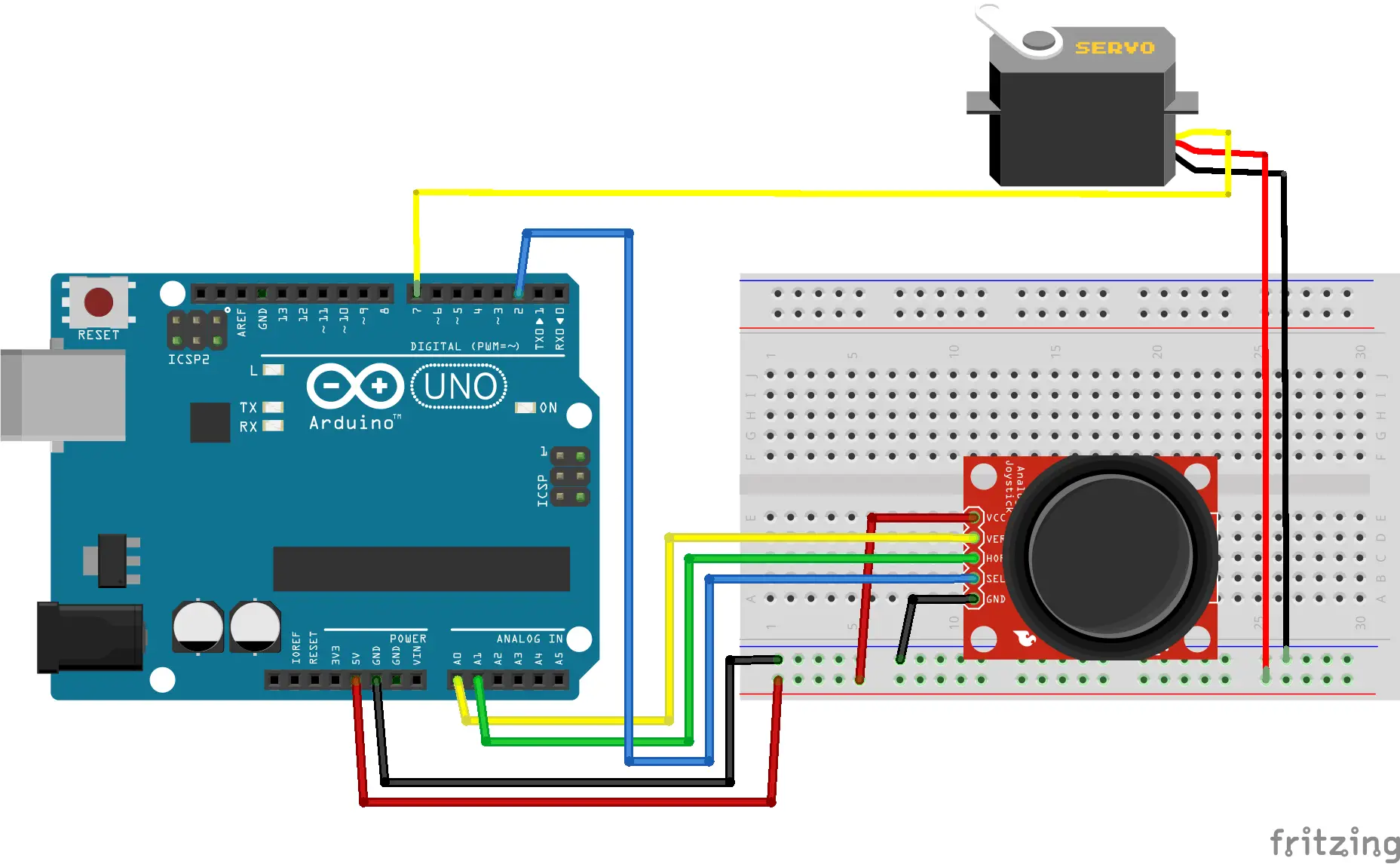
Controlling a Servo with Joystick in Arduino
Servo Wiring and Coding Basics with Arduino. The MG90S is another small servo motor that is similar to the SG90, but weighs slightly more (14g) and has metal gears instead of plastic. The MG90S is also slightly faster than the SG90, which is a further justification for why it is used here. Both the MG90S and the SG90 are wired the same and use.

SG90 Servo Motor Pinout Arduino sensors, Microcontrollers
MG995 Servo Motor Pinout MG995 is a durable double ball bearing servo motor. The diagram shown below is the pinout of the MG995 Servo Motor: MG995 Pin Configuration It is a three terminal device.The pin configuration detail in tabular is mentioned below: MG995 Features and Specifications Operating Voltage: 4.8 - 7.2 Volts

Servo Motor Wiring Diagram merrell menshoes purchase
PWM is an ideal control medium. It can be generated by a simple timer circuit or with a microcontroller. It can be sent over a single wire or transmitted on a radio or light beam.
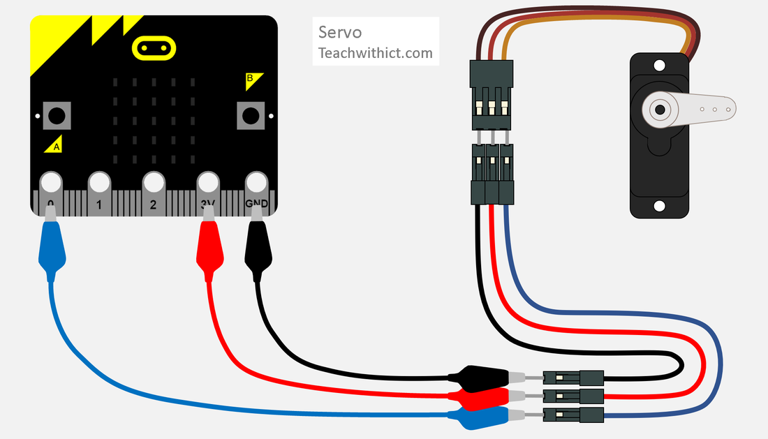
How to attach a Servo to a microbit
The Knob Circuit. Sweep Circuit For the Sweep example, connect the servo motor as shown in the circuit below. The Sweep Circuit. Examples Knob Controlling a servo position using a potentiometer (variable resistor). 1 #include
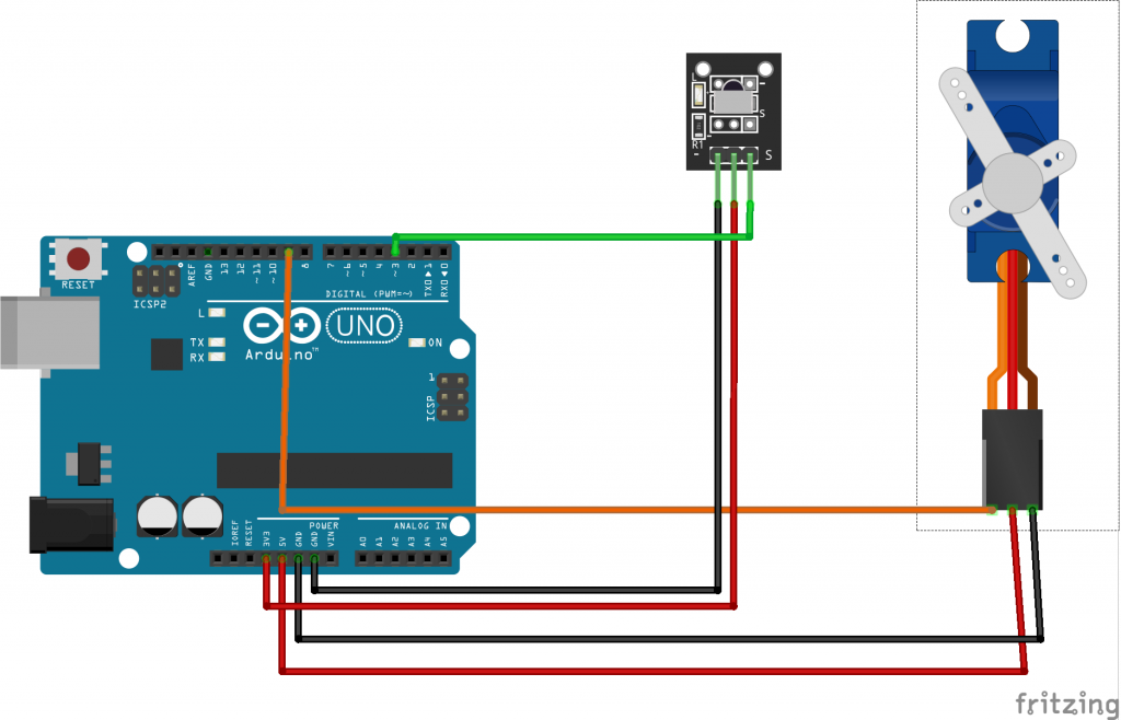
Arduino lesson Controlling Servo Motor with IR Remote «
The pinout of the SG90 servo is as follows. GND Is a common ground for both the motor and microcontroller. VCC is the supply voltage that powers the servo. Control is the input from a microcontroller or any other control mechanism.

Servo Wiring Diagram Arduino
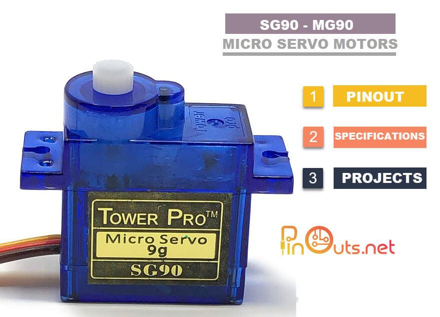
The SG90 is a 9g micro servo motor with a torque of 1.8 kg/cm and a rotation angle of approximately 180 degrees. The main application of SG90 Servo Motors is in small-scale hobby projects such as remote-controlled cars, robots, and aircraft. These motors can be used to control the position of the steering wheel, flaps, and other parts that need.
Arduino Servo Motor Arduino Tutorial (2022)
Connector Pinout One of the most important things to make note of with any servo is the pinout of the connector in order to prevent wiring things up incorrectly. Most servos follow a specific color-code for Power ( VCC ), Ground ( GND) and Control Signal.
GitHub RamsesOrtiz36/ServoESP32CAM Control de un Servo motor con el
Arduino example code How the code works Control angle/position: Control speed: Why doesn't my servo turn a full 0 - 180 degrees? Control a servo motor with a potentiometer and Arduino Servo motor with potentiometer Arduino example code Controlling multiple servo motors Arduino with multiple servos example code Servo motor specifications
Servo Motor Sg90 Arduino Datasheet
They're set up for servos but you can use them for LEDs! Max current per pin is 25mA. There are 220 ohm resistors in series with all PWM Pins and the output logic is the same as VCC so keep that in mind if using LEDs. Overview Assembly This guide was first published on Oct 16, 2012. It was last updated on Jan 07, 2024.
How to use a SG90 / SG90 Servo with an Arduino Bot Universe
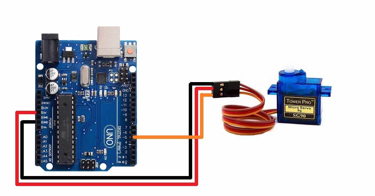
Wiring Servo Motor to Arduino UNO. To connect the servo motor to the Arduino, follow these steps: We will be using an SG90 Micro Servo Motor for our experiments. This servo motor operates on a voltage range of 4.8-6VDC, with 5V being the typical voltage. It has a rotation capability of 180 degrees, with 90 degrees in each direction.